_edit.png)
3D Printing Workflow Overview
- Jun 12, 2025
- 1 min read
1. Produce a 3D CAD model of the part you want to print.

2. The CAD model (usually in stl or 3mf file format) is imported into a slicer software which produces code that the printer can understand and use as instructions (usually a gcode file).
The slicer software does what the name suggests - it slices a 3D model into layers that can be treated as 2D representations of the part.
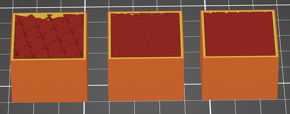
Slicer is also where the print settings are set based on the geometry, function and material used. For example, variables like infill percentage and layer thickness.
The slicer also detects and produces part supports where needed (with some manual intervention).

3. Printer produces the part following the instructions in the file from the slicer software.
4. Part is removed from the printer and post-processed as required.
For FDM prints this usually means removing build supports if they are used.
For resin prints this means removing build supports, washing the part to remove excess resin and curing the part before they are ready for use.